前言#
通过缓冲区来一次定义顶点数据,通过可变变量认识顶点和片元作色器数据流,初始图形光栅化流程。最后学习纹理贴图技巧。
如何向顶点作色器传入非坐标数据#
在开始介绍光栅化和贴图之前,我们先重新认识下 gl.vertexAttribPointer 方法。
如何绘制三个不同大小的点?#
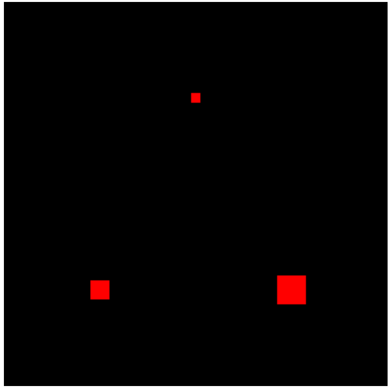
先前,我们是通过缓冲区对象来实现给顶点着色器中的坐标变量绘制多个顶点,现在也通过一样的方法来设置非坐标类的数据,比如点的大小。
首先我们要定义一个新的 attribute 变量 a_PointSize ,和坐标 a_Position 不同,它是一个 float 类型:
var VSHADER_SOURCE = `
  attribute vec4 a_Position;
  attribute float a_PointSize;
  void main() {
    gl_Position = a_Position;
    gl_PointSize = a_PointSize;
  }`;
然后在 initVertexBuffers() 初始化缓冲区方法中,为变量 a_PointSize 创建缓冲区,并设置数据,这和为a_Position 创建缓冲区逻辑一样:
function main() {
  // init gl ...
  // init shaders ...

  // Set the vertex information
  var n = initVertexBuffers(gl);

  // draw ...
}
function initVertexBuffers(gl) {
  var vertices = new Float32Array([0.0, 0.5, -0.5, -0.5, 0.5, -0.5]);
  var n = 3;

  var sizes = new Float32Array([
    10.0,
    20.0,
    30.0, // Point sizes
  ]);

  // Create a buffer object
  var vertexBuffer = gl.createBuffer();
  var sizeBuffer = gl.createBuffer();

  // 设置顶点坐标缓存区逻辑
  gl.bindBuffer(gl.ARRAY_BUFFER, vertexBuffer);
  gl.bufferData(gl.ARRAY_BUFFER, vertices, gl.STATIC_DRAW);
  var a_Position = gl.getAttribLocation(gl.program, "a_Position");
  // 2个一取
  gl.vertexAttribPointer(a_Position, 2, gl.FLOAT, false, 0, 0);
  gl.enableVertexAttribArray(a_Position);

  // 设置颜色缓冲区
  gl.bindBuffer(gl.ARRAY_BUFFER, sizeBuffer);
  gl.bufferData(gl.ARRAY_BUFFER, sizes, gl.STATIC_DRAW);
  var a_PointSize = gl.getAttribLocation(gl.program, "a_PointSize");
  // 1个一取
  gl.vertexAttribPointer(a_PointSize, 1, gl.FLOAT, false, 0, 0);
  gl.enableVertexAttribArray(a_PointSize);

  // Unbind the buffer object
  gl.bindBuffer(gl.ARRAY_BUFFER, null);

  return n;
}
gl.vertexAttribPointer 的步进和偏移#
上例很容易就实现了,但注意到里面对顶点坐标和点的大小分别定义了两个数组,假如我们有几百,上千个顶点数据将会很困难。
对于 gl.vertexAttribPointer 它提供了一种 交错组织(interleaving) 的方式进行优化,我们可以设置 步进 和 偏移 来对代码进行改造。
gl.vertexAttribPointer(index, size, type, normalized, stride, offset) :
- index: 顶点属性的索引,对应 gl.bindAttribLocation() 中设置的索引。
- size: 顶点属性的大小。
- type: 顶点属性的数据类型。
- normalized: 是否归一化数据。
- stride: 顶点属性在缓存区中的步进,即相邻顶点属性之间的字节数。
- offset: 顶点属性在缓存区中的偏移量,即从缓存区开始到第一个顶点属性的起始位置。
首先我们调整数据集合 verticesSizes ,将两种数据进行合并:
// prettier-ignore
var verticesSizes = new Float32Array([
    // Coordinate and size of points
     0.0,  0.5,  10.0,  // the 1st point
    -0.5, -0.5,  20.0,  // the 2nd point
     0.5, -0.5,  30.0   // the 3rd point
  ]);
每三个数据定义为一组,依次来描述顶点坐标和大小(FSIZE * 3)。即对于顶点坐标每次取前 2 个字节作为坐标值,对于大小则每次取 1 个字节作为顶点值。
由于顶点大小的值位于每组数据的第三位,则需要通过 FSIZE * 2 来偏移。那么 gl.vertexAttribPointer 将按如下定义:
// 每个顶点数据占字节数
var FSIZE = verticesSizes.BYTES_PER_ELEMENT;

// 创建和绑定缓存区...
gl.vertexAttribPointer(a_Position, 2, gl.FLOAT, false, FSIZE * 3, 0);
gl.enableVertexAttribArray(a_Position); // Enable the assignment of the buffer object

// 创建和绑定缓存区...
gl.vertexAttribPointer(a_PointSize, 1, gl.FLOAT, false, FSIZE * 3, FSIZE * 2);
gl.enableVertexAttribArray(a_PointSize); // Enable buffer allocation
图形的光栅化过程#
顶点和片元着色器的纽带:varying#
现在我们尝试绘制一个三个不同色的点:
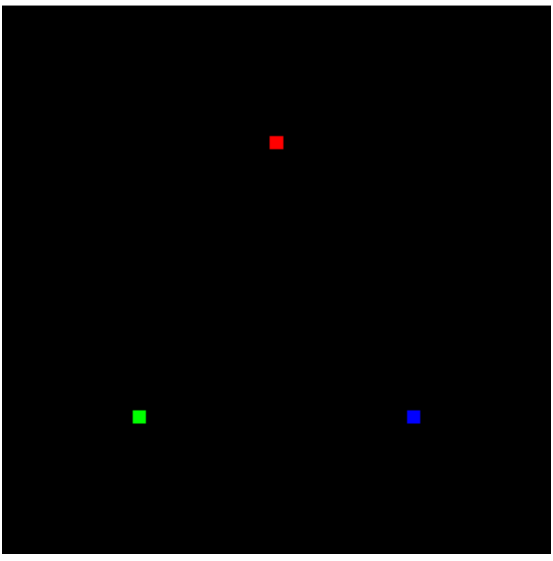
之前,我们定义图形颜色都是在片元作色器中通过 uniform (一致的)定义颜色变量。现在由于需要绘绘制不同颜色的点,则需要通过一个可变化的变量来修饰。
首先在顶点作色器中定义一个 varying 颜色变量 v_Color:
var VSHADER_SOURCE =
  "attribute vec4 a_Position;\n" +
  "attribute vec4 a_Color;\n" +
  "varying vec4 v_Color;\n" + // varying variable
  "void main() {\n" +
  "  gl_Position = a_Position;\n" +
  "  gl_PointSize = 10.0;\n" +
  "  v_Color = a_Color;\n" + // Pass the data to the fragment shader
"}\n";然后在光栅化后,v_Color 将传给片元作色器中,片元作色器读取 v_Color 并使用它来渲染图形:
var FSHADER_SOURCE =
  "precision mediump float;\n" + // Precision qualifier (See Chapter 6)
  "varying vec4 v_Color;\n" + // Receive the data from the vertex shader
  "void main() {\n" +
  "  gl_FragColor = v_Color;\n" +
  "}\n";
主函数 main 流程还是不变,将在 initVertexBuffers 方法中处理颜色逻辑:
function main() {
  // 初始化 gl
  var canvas = document.getElementById("webgl");
  var gl = getWebGLContext(canvas);

  // Initialize shaders
  if (!initShaders(gl, VSHADER_SOURCE, FSHADER_SOURCE)) {
    console.log("Failed to intialize shaders.");
    return;
  }

  // 初始化顶点数据
  var n = initVertexBuffers(gl);

  // draw
  gl.clearColor(0.0, 0.0, 0.0, 1.0);
  gl.clear(gl.COLOR_BUFFER_BIT);
  gl.drawArrays(gl.POINTS, 0, n);
}
这里一起定义了 verticesColors :顶点坐标值和色值(每组 5 条数据),并通过 gl.vertexAttribPointer 处理了数据分配方式:
function initVertexBuffers(gl) {
  // prettier-ignore
  var verticesColors = new Float32Array([
    // Vertex coordinates and color
    0.0, 0.5, 1.0, 0.0, 0.0,
    -0.5, -0.5, 0.0, 1.0, 0.0,
    0.5, -0.5, 0.0, 0.0, 1.0,
  ]);
  var n = 3; // The number of vertices

  // Create a buffer object
  var vertexColorBuffer = gl.createBuffer();

  // Write the vertex coordinates and colors to the buffer object
  gl.bindBuffer(gl.ARRAY_BUFFER, vertexColorBuffer);
  gl.bufferData(gl.ARRAY_BUFFER, verticesColors, gl.STATIC_DRAW);

  var FSIZE = verticesColors.BYTES_PER_ELEMENT;
  //Get the storage location of a_Position, assign and enable buffer
  var a_Position = gl.getAttribLocation(gl.program, "a_Position");
  gl.vertexAttribPointer(a_Position, 2, gl.FLOAT, false, FSIZE * 5, 0);
  gl.enableVertexAttribArray(a_Position); // Enable the assignment of the buffer object

  // Get the storage location of a_Position, assign buffer and enable
  var a_Color = gl.getAttribLocation(gl.program, "a_Color");
  gl.vertexAttribPointer(a_Color, 3, gl.FLOAT, false, FSIZE * 5, FSIZE * 2);
  gl.enableVertexAttribArray(a_Color); // Enable the assignment of the buffer object

  return n;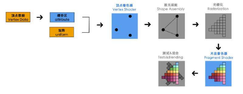
}图形装配和光栅化#
我们每个图形渲染,在着色器内部会经历几个步骤:
- 图形装配:通过顶点坐标,根据 gl.drawArrays 设置的 webgl 基本图形装配成几何图形(这些点线面的简单图形成为图元)
- 光栅化:将几何图形转化为片元(一个个正方形的像素)
- 调用片元着色器:通过片元着色器对光栅化的每个像素逐个进行处理,直至显示
可以试着改变 gl.drawArrays 的 mode 为 gl.TRIANGLES,能看到呈现出颜色平滑过渡的三角形:
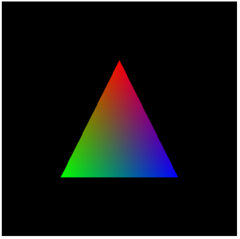
gl.drawArrays(gl.TRIANGLES, 0, n);虽然我们只维护了顶点的三个颜色,但对于所有片元,他们各自的颜色会通过 内插过程(interpolation process) 进行计算,再交给 v_Color 变量。 webgl 会选择一个合适的颜色。
为了说明片元作色器是逐片渲染,我们可以通过 gl_FragCoord.x 和 gl_FragCoord.y 来获取当前片元的位置,并通过和图形的长宽的比例进行归一化,将坐标映射到屏幕:
// prettier-ignore
var VSHADER_SOURCE =
  'attribute vec4 a_Position;\n' +
  'void main() {\n' +
  '  gl_Position = a_Position;\n' +
  '}\n';

// Fragment shader program
var FSHADER_SOURCE =
  "precision mediump float;\n" +
  "uniform float u_Width;\n" +
  "uniform float u_Height;\n" +
  "void main() {\n" +
  "  gl_FragColor = vec4(gl_FragCoord.x/u_Width, 0.0, gl_FragCoord.y/u_Height, 1.0);\n" +
  "}\n";
function initVertexBuffers(gl) {
var vertices = new Float32Array([0, 0.5, -0.5, -0.5, 0.5, -0.5]);
// ...
var u_Width = gl.getUniformLocation(gl.program, "u_Width");
var u_Height = gl.getUniformLocation(gl.program, "u_Height");
gl.uniform1f(u_Width, gl.drawingBufferWidth);
gl.uniform1f(u_Height, gl.drawingBufferHeight);
gl.enableVertexAttribArray(a_Position);
gl.bindBuffer(gl.ARRAY_BUFFER, null);
return n;
}能看到最终是一个渐变色的图形: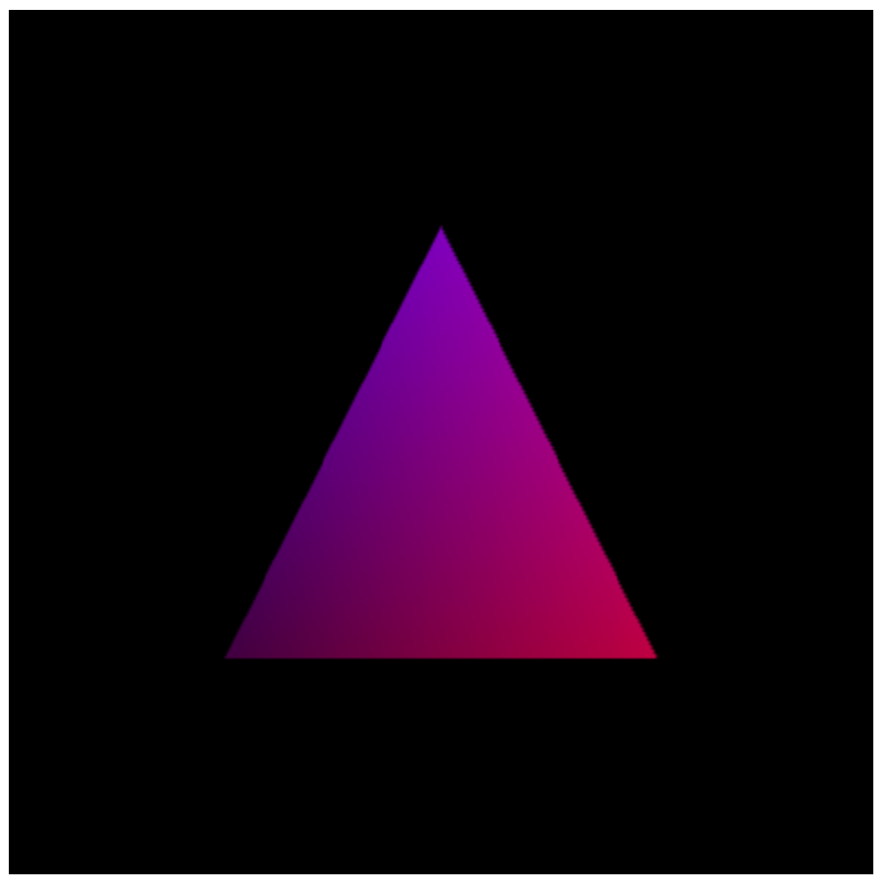
纹理贴图#
为了更真实的展示图形外观,我们可以通过 纹理映射(texture mapping) 来给几何图形添加纹理,即:将一张图片贴到几何图形表面上,这样我们就能得到一个带有纹理的图形。
如何实现纹理映射?#
首先我们贴到图形上的图片成为纹理图像,该图像有他对应的坐标体系来定义,称为 纹理坐标(st 坐标,以原点为起点,按 s 横坐标,t 纵坐标的正方向来定义图片。我们 webgl 的图形是以原点为中心)。
比如绘制这样一个纹理图像: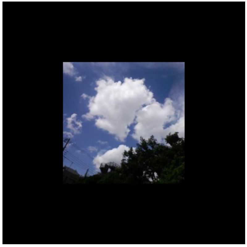
首先在顶点着色器中定义一个可变的纹理变量 v_TexCoord ,并在光栅化后交给片元着色器中读取。
// prettier-ignore
var VSHADER_SOURCE =
  'attribute vec4 a_Position;\n' +
  'attribute vec2 a_TexCoord;\n' +
  'varying vec2 v_TexCoord;\n' +
  'void main() {\n' +
  '  gl_Position = a_Position;\n' +
  '  v_TexCoord = a_TexCoord;\n' +
  '}\n';
在片元着色器中,通过 texture2D() 来抽取纹理颜色,其中 u_Sampler 是一个纹理采样器,用于从纹理贴图中获取颜色。v_TexCoord 就是和前面绘制不同色顶点示例中定义的可变变量类似,只是现在是纹理变量。
// Fragment shader program
var FSHADER_SOURCE = `
  #ifdef GL_ES
    precision mediump float;
  #endif
  uniform sampler2D u_Sampler;
  varying vec2 v_TexCoord;
  void main() {
    gl_FragColor = texture2D(u_Sampler, v_TexCoord);
  }`;
这是主函数逻辑:
function main() {
  // 初始化 gl
  var canvas = document.getElementById("webgl");
  var gl = getWebGLContext(canvas);

  // Initialize shaders
  if (!initShaders(gl, VSHADER_SOURCE, FSHADER_SOURCE)) {
    console.log("Failed to intialize shaders.");
    return;
  }

  // Set the vertex information
  var n = initVertexBuffers(gl);

  gl.clearColor(0.0, 0.0, 0.0, 1.0);

  // 初始化纹理对象
  if (!initTextures(gl, n)) {
    console.log("Failed to intialize the texture.");
    return;
  }
}
在 initVertexBuffers 中联合定义顶点坐标和纹理坐标数据集合,并通过缓冲区对象将数据传入 a_Position 和 a_TexCoord 变量:
function initVertexBuffers(gl) {
  // 顶点:前两个是顶点坐标,后两个是纹理坐标
  // prettier-ignore
  var verticesTexCoords = new Float32Array([
    // Vertex coordinates, texture coordinate
    -0.5,  0.5,   0.0, 1.0,
    -0.5, -0.5,   0.0, 0.0,
     0.5,  0.5,   1.0, 1.0,
     0.5, -0.5,   1.0, 0.0,
  ]);
  var n = 4; // The number of vertices

  // 创建缓冲区
  var vertexTexCoordBuffer = gl.createBuffer();
  gl.bindBuffer(gl.ARRAY_BUFFER, vertexTexCoordBuffer);
  gl.bufferData(gl.ARRAY_BUFFER, verticesTexCoords, gl.STATIC_DRAW);

  // 作用顶点坐标
  var FSIZE = verticesTexCoords.BYTES_PER_ELEMENT;
  var a_Position = gl.getAttribLocation(gl.program, "a_Position");
  gl.vertexAttribPointer(a_Position, 2, gl.FLOAT, false, FSIZE * 4, 0);
  gl.enableVertexAttribArray(a_Position);

  // 作用纹理坐标
  var a_TexCoord = gl.getAttribLocation(gl.program, "a_TexCoord");
  gl.vertexAttribPointer(a_TexCoord, 2, gl.FLOAT, false, FSIZE * 4, FSIZE * 2);
  gl.enableVertexAttribArray(a_TexCoord); // Enable the assignment of the buffer object

  return n;
}
initVertexBuffers 处理后,将调用 initTextures,通过 gl.createTexture 创建纹理对象,并通过 Image 加载纹理图片:
function initTextures(gl, n) {
  // 1. 创建纹理图像,用来存储图片
  var texture = gl.createTexture(); // Create a texture object
  if (!texture) {
    console.log("Failed to create the texture object");
    return false;
  }

  // 2. 获取片元作色器中,取样变量 u_Sampler
  var u_Sampler = gl.getUniformLocation(gl.program, "u_Sampler");
  if (!u_Sampler) {
    console.log("Failed to get the storage location of u_Sampler");
    return false;
  }
  // 3. 加载图片
  var image = new Image(); // Create the image object
  if (!image) {
    console.log("Failed to create the image object");
    return false;
  }
  // Register the event handler to be called on loading an image
  image.onload = function () {
    loadTexture(gl, n, texture, u_Sampler, image);
  };
  // Tell the browser to load an image
  image.src = "../resources/sky.jpg";

  return true;
}
图片加载时会调用 loadTexture 来使得图片存储到纹理对象中,但要经过一系列步骤:
- gl.pixelStorei:由于 Image 的图片坐标和 WebGL 的纹理坐标系 Y 轴相反,所以调用
gl.pixelStorei翻转纹理坐标。 - gl.activeTexture:激活第一个纹理单元 0
- gl.bindTexture:绑定纹理对象
- gl.texParameteri:定义为二维纹理类型
gl.TEXTURE_2D,约定纹理按那种样式绘制(gl.TEXTURE_MIN_FILTER缩小图片),以及样式的值(gl.LINEAR线性插值) - gl.texImage2D:将纹理图像分配给纹理对象,设置文素数据格式
- 传入到 webgl 里的 u_Sampler 变量
- 清空并绘制
function loadTexture(gl, n, texture, u_Sampler, image) {
  gl.pixelStorei(gl.UNPACK_FLIP_Y_WEBGL, 1); // Flip the image's y axis
  // Enable texture unit0
  gl.activeTexture(gl.TEXTURE0);
  // Bind the texture object to the target
  gl.bindTexture(gl.TEXTURE_2D, texture);

  // Set the texture parameters
  gl.texParameteri(gl.TEXTURE_2D, gl.TEXTURE_MIN_FILTER, gl.LINEAR);
  // Set the texture image
  gl.texImage2D(gl.TEXTURE_2D, 0, gl.RGB, gl.RGB, gl.UNSIGNED_BYTE, image);

  // Set the texture unit 0 to the sampler
  gl.uniform1i(u_Sampler, 0);

  gl.clear(gl.COLOR_BUFFER_BIT); // Clear <canvas>

  gl.drawArrays(gl.TRIANGLE_STRIP, 0, n); // Draw the rectangle
}纹理方法#
gl.texParameteri(gl.TEXTURE_2D, gl.TEXTURE_MIN_FILTER, gl.LINEAR);
gl.texParameteri(target, pname, param);
- target: 纹理对象,gl.TEXTURE_2D 或 gl.TEXTURE_CUBE_MAP
- pname: 纹理参数
    gl.TEXTURE_MIN_FILTER 纹理缩小,默认值:gl.LINEAR
    gl.TEXTURE_MAG_FILTER 纹理放大,默认值:gl.NEAREST_MIPMAP_LINEAR
    gl.TEXTURE_WRAP_S 纹理水平方向的坐标超出范围时,默认值:gl.REPEAT
    gl.TEXTURE_WRAP_T 纹理垂直方向的坐标超出范围时,默认值:gl.REPEAT
- param: 纹理参数值,gl.LINEAR、gl.NEAREST、gl.NEAREST_MIPMAP_LINEAR、gl.LINEAR_MIPMAP_LINEAR、gl.REPEAT、gl.MIRRORED_REPEAT、gl.CLAMP_TO_EDGE
gl.texImage2D(gl.TEXTURE_2D, 0, gl.RGB, gl.RGB, gl.UNSIGNED_BYTE, image);
gl.texImage2D(target, level, internalFormat, format, type, image)
- target: 纹理对象,gl.TEXTURE_2D 或 gl.TEXTURE_CUBE_MAP
- level: 纹理的级别,默认值:0
- internalFormat: 纹理内部格式,gl.RGB、gl.RGBA、gl.ALPHA、gl.LUMINANCE、gl.LUMINANCE_ALPHA
- format: 纹理格式,gl.RGB、gl.RGBA、gl.ALPHA、gl.LUMINANCE、gl.LUMINANCE_ALPHA
- type: 纹理数据类型,gl.UNSIGNED_BYTE、gl.UNSIGNED_SHORT_5_6_5、gl.UNSIGNED_SHORT_4_4_4_4、gl.UNSIGNED_SHORT_5_5_5_1
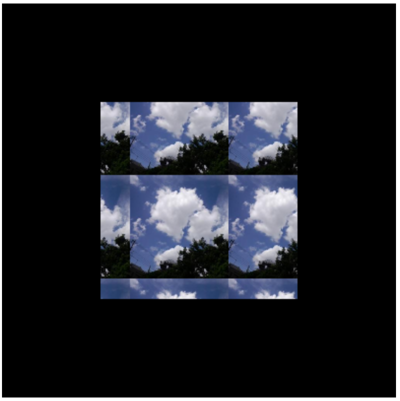
- image: 纹理图片repeat 效果#
当纹理坐标和顶点坐标不匹配时(纹理坐标的框子大于顶点坐标),那会产生类似 css 里 repeat 的效果:
// prettier-ignore
var verticesTexCoords = new Float32Array([
    -0.5,  0.5,   -0.3, 1.7,
    -0.5, -0.5,   -0.3, -0.2,
     0.5,  0.5,   1.7, 1.7,
     0.5, -0.5,   1.7, -0.2
  ]);
多次修饰纹理样式#
比如我们将纹理参数设置为如下方式:
// 纹理会按照线性方式缩小
gl.texParameteri(gl.TEXTURE_2D, gl.TEXTURE_MIN_FILTER, gl.LINEAR);
// 纹理坐标中的垂直轴,图形按照镜像方式重复
gl.texParameteri(gl.TEXTURE_2D, gl.TEXTURE_WRAP_T, gl.MIRRORED_REPEAT);
// 纹理坐标中的水平轴,图形按边缘值填充
gl.texParameteri(gl.TEXTURE_2D, gl.TEXTURE_WRAP_S, gl.CLAMP_TO_EDGE);
纹理图像会展示成这样: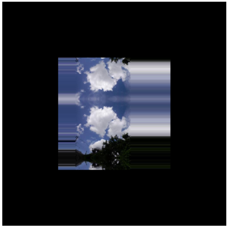
多幅纹理贴图#
在前面纹理图像上再增加一个蓝色贴图:
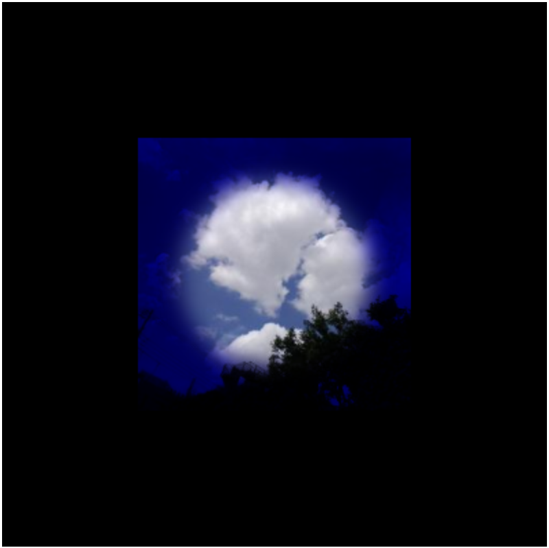
首先修改片元着色器,分别定义 2 个可变的颜色矢量,通过相乘的方式产生新的矢量分量来表示贴图的叠加:
var FSHADER_SOURCE =
  "#ifdef GL_ES\n" +
  "precision mediump float;\n" +
  "#endif\n" +
  "uniform sampler2D u_Sampler0;\n" +
  "uniform sampler2D u_Sampler1;\n" +
  "varying vec2 v_TexCoord;\n" +
  "void main() {\n" +
  "  vec4 color0 = texture2D(u_Sampler0, v_TexCoord);\n" +
  "  vec4 color1 = texture2D(u_Sampler1, v_TexCoord);\n" +
  "  gl_FragColor = color0 * color1;\n" +
  "}\n";
定义 2 个纹理对象,通过 Image 来加载多个纹理图形:
function initTextures(gl, n) {
  // Create a texture object
  var texture0 = gl.createTexture();
  var texture1 = gl.createTexture();

  // Get the storage location of u_Sampler0 and u_Sampler1
  var u_Sampler0 = gl.getUniformLocation(gl.program, "u_Sampler0");
  var u_Sampler1 = gl.getUniformLocation(gl.program, "u_Sampler1");

  // Create the image object
  var image0 = new Image();
  var image1 = new Image();

  // Register the event handler to be called when image loading is completed
  image0.onload = function () {
    loadTexture(gl, n, texture0, u_Sampler0, image0, 0);
  };
  image1.onload = function () {
    loadTexture(gl, n, texture1, u_Sampler1, image1, 1);
  };
  // Tell the browser to load an Image
  image0.src = "../resources/sky.jpg";
  image1.src = "../resources/circle.gif";

  return true;
}
通过切换来状态激活纹理,依次设置纹理图像:
// Specify whether the texture unit is ready to use
var g_texUnit0 = false,
  g_texUnit1 = false;
function loadTexture(gl, n, texture, u_Sampler, image, texUnit) {
  gl.pixelStorei(gl.UNPACK_FLIP_Y_WEBGL, 1); // Flip the image's y-axis
  // Make the texture unit active
  if (texUnit == 0) {
    gl.activeTexture(gl.TEXTURE0);
    g_texUnit0 = true;
  } else {
    gl.activeTexture(gl.TEXTURE1);
    g_texUnit1 = true;
  }

  gl.bindTexture(gl.TEXTURE_2D, texture);
  gl.texParameteri(gl.TEXTURE_2D, gl.TEXTURE_MIN_FILTER, gl.LINEAR);
  gl.texImage2D(gl.TEXTURE_2D, 0, gl.RGBA, gl.RGBA, gl.UNSIGNED_BYTE, image);

  gl.uniform1i(u_Sampler, texUnit); // Pass the texure unit to u_Sampler

  // Clear <canvas>
  gl.clear(gl.COLOR_BUFFER_BIT);

  if (g_texUnit0 && g_texUnit1) {
    gl.drawArrays(gl.TRIANGLE_STRIP, 0, n); // Draw the rectangle
  }
}